Lcp2 Control Panel Wiring Diagram
447d81b Fg Wilson Control Panel Wiring Diagram Wiring Resources
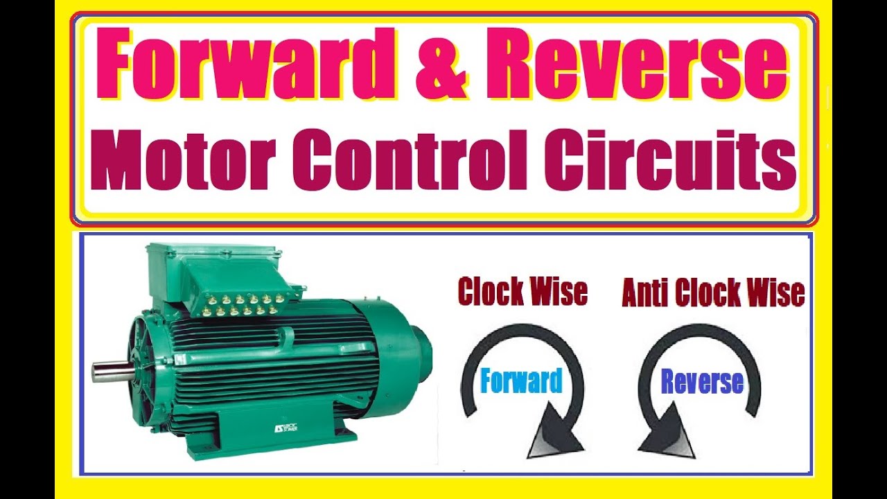
Wiring Diagram Motor Forward Reverse Diagram Base Website Forward
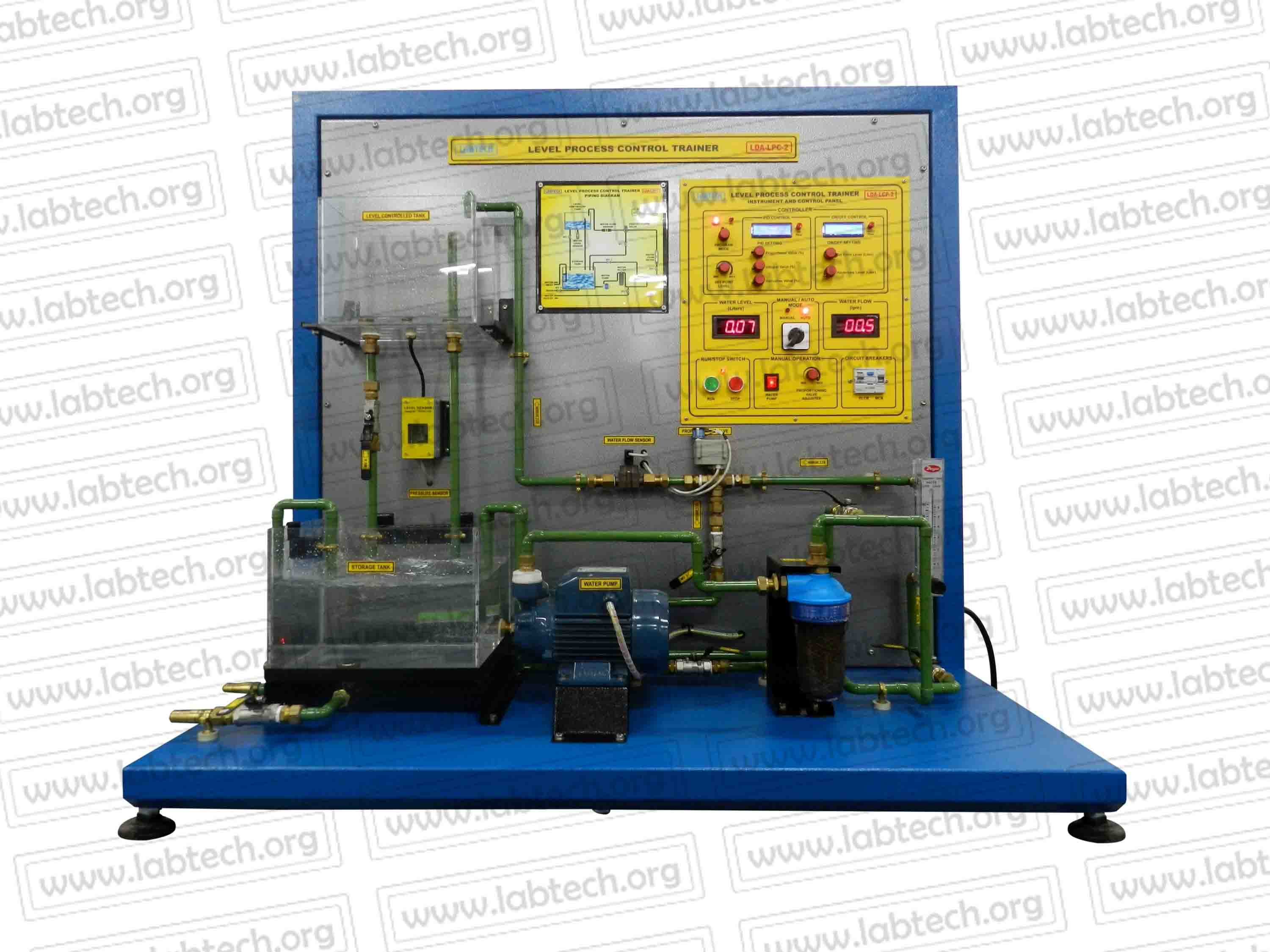
Data Acquisition Instrumentation Process Control Trainers
Http Files Danfoss Com Download Drives Mg27e402 Pdf
Https Www Lasermax Com Pub Media Lm Files Gs Lcp 2 Manual 01785 0 69b Web Pdf

Nokia 2160 Service Manual Install
Lighting control panel using contactor and relay what is a lighting control panel.
Lcp2 control panel wiring diagram. Ave libis quezon city philippines. Wiring diagrams sometimes called main or construction diagrams show the actual connection points for the wires to the components and terminals of the controller. Fg wilson prime parts. Works directly with incandescent magnetic low voltage reverse phase electronic low voltage.
All wires and components are numbered and are referenced on the schematic. Wiring diagram included along with the schematic diagram is a wiring diagram and panel internal layout. Control panel lcp2 the lcp2 control panel is designed for automatic starting and stopping of the generating set with 2 wire remote contacts as well as manual starting and stopping. The control system provides.
Astronomical time clock provides automated selection of lighting scenes. Entire system is programmed using the lcd controller mounted in the panel. With these three diagrams it is a simple matter to find the components and their. Lcp100 local control panel may 2020 8 figure 5.
The contacts m will be controlled by the coil m the output of the motor starter goes to a three phase ac motor. Ex e mb ib iic or ex tb iiic wiring diagram 1 lcp100 protection method lcp100 power source wiring order from logic solver dvc6200 sis mode current or voltage ex e mb ib iic ex tb iiic loop dvc6200 sis then lcp100 point to point 2 logic solver output 8 20 ma user supplied 1 notes. 2 f the gallery building 80 e. 1027 1028 lights groups scenes support fifth light technology 11 46 06 26 09 1000 2 1 3 4 lighting control panel.
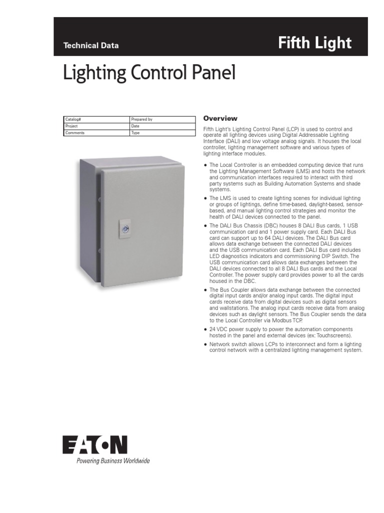
The panel provides instrumentation for volts amps and a combined frequency meter and tachometer along with a battery condition voltmeter. Connect up to 32 wallstations or control devices for multiple points of control. Get to grips quickly with the operation and control of your generator set with safe easy to use control from a range of keystart automatic digital and synchronising control panel systems. Lighting control panel wwweatoncomligtingsystems wiring diagram nnoee sample wiring diagram for a lcpa model sample system topology ethernet dali dac 0 10 vdc dali dimmable ballast dali multi sensor 10 10 20 30 40 units are.
Lcp2 control panel. Power is supplied by connecting a step down transformer to the control electronics by connecting to phases l2 and l3. The lower voltage is then used to supply power to the left and right rails of the ladder below. Figure 1 a motor controller schematic.
A lighting control system is an intelligent network based lighting control solution that incorporates. These show the approximate physical layout of the control components and their wiring. We also offer remote communications capability on selected control panels.
Https Library E Abb Com Public 6e8b7ab0f6e947f197c15adc06e141d6 Re 615 Oper 756708 Enn Pdf
Https Www Altraliterature Com Media Files Literature Brand Bauer Gear Motor Service Manuals P 7132 Bgm En A5 Ashx

Ruger Lcp 2 Trigger Spring Kit For Ruger Lcp 2 Accessories
Control And Analysis Of Bidirectional Interleaved Hybrid Converter

Ruger Lcp Lcp Ii Extra Power Mag Release Spring

Ruger Lcp 2 Grips Textured Rubber Adhesive Best Fit Ruger Lcp 2
Http Files Danfoss Com Download Drives Mg33bf22 Pdf
Https Library E Abb Com Public 35883b9b04b841ea8ebcec22068f9d7d Rex640 Inst 759115 Enc Pdf
Http Files Danfoss Com Download Drives Doc A 1 Mg90f222 Pdf
Https Library E Abb Com Public 935511e718684db888a2c910b98060a0 511346 Uen Um Pwc600i 1p0 Pdf

Xr 1971 Electrical Control Panel Wiring Diagram On Electrical