Mallory 5048201 Wiring Diagram
Mallory 5048201 Wiring Diagram Wiring Diagram

Mallory Unilite Wiring Diagram Sbc Diagrams Schematics Inside

Mallory 8548201 Hei Wiring Diagram Lari Fuse8 Klictravel Nl

Big 3 Upgrade Diagram Luxury Collection Big 3 Wire Upgrade Diagram

Pin On Patrick Lothrop

Wiring Diagram For 220 Volt Single Phase Motor With Images Ac

Thank you for your question.
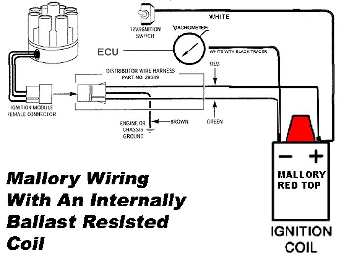
Mallory 5048201 wiring diagram. The purpose of resistance wire between the ignition switch 12v and the ignition coil positive terminal is to restrict current flow through the ignition coil. The purpose of resistance wire between the ignitionswitch 12v and the ignition coil positive terminal is to restrictcurrent flow through the ignition coil. Mallory promaster coil wiring diagram wiring diagram is a simplified welcome pictorial representation of an electrical circuit it shows the components of the circuit as simplified shapes and the capability and signal contacts amongst the devices. Collection of mallory ignition wiring diagram.
Coil figure 2 unilite wiring diagram using oem primary resistance wire note. Failure to use resistancewire will eventually destroy the ignition module exception. Mallory 5048201 wiring diagram wire arresting marine distributor 11 mallory ignition wiring diagram hei distributor data in marine 10 mallory distributor wiring diagram in ignition to 5 marine 9 mallory wiring diagram 351 data simple marine distributor 8 mallory marine distributor wiring diagram natebird me fancy 7 unilite. All mallory unilite and breakerless distributors require an ignition coil with 1 4 ohms of resistance or 7 ohms resistor along with a low resistance coil.
A wiring diagram is a simplified standard pictorial depiction of an electrical circuit. If you want to find the other picture or article about mallory promaster. Mallory wiring diagram 351 data amazing marine distributor 2. How do i wire my mallory distributor.
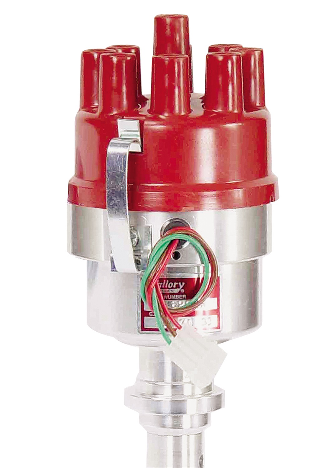
Mallory 5048201 is no longer available. 5048201 mallory magnetic breakerless ignition v8 small block 50 series distributor mechanical advance this distributor uses mallory s mbi magnetic breakerless ignition triggering system and can trigger either a hyfire capacitive discharge ignition or be run with just a coil. If your vehicle is equipped with a hyfire.

Taylor Dunn Wiring Diagram Volovets Info Chevy Trucks

Micro820 Plc Wiring Diagram Caca Fantasmas Coisas Fofas Aleatorias
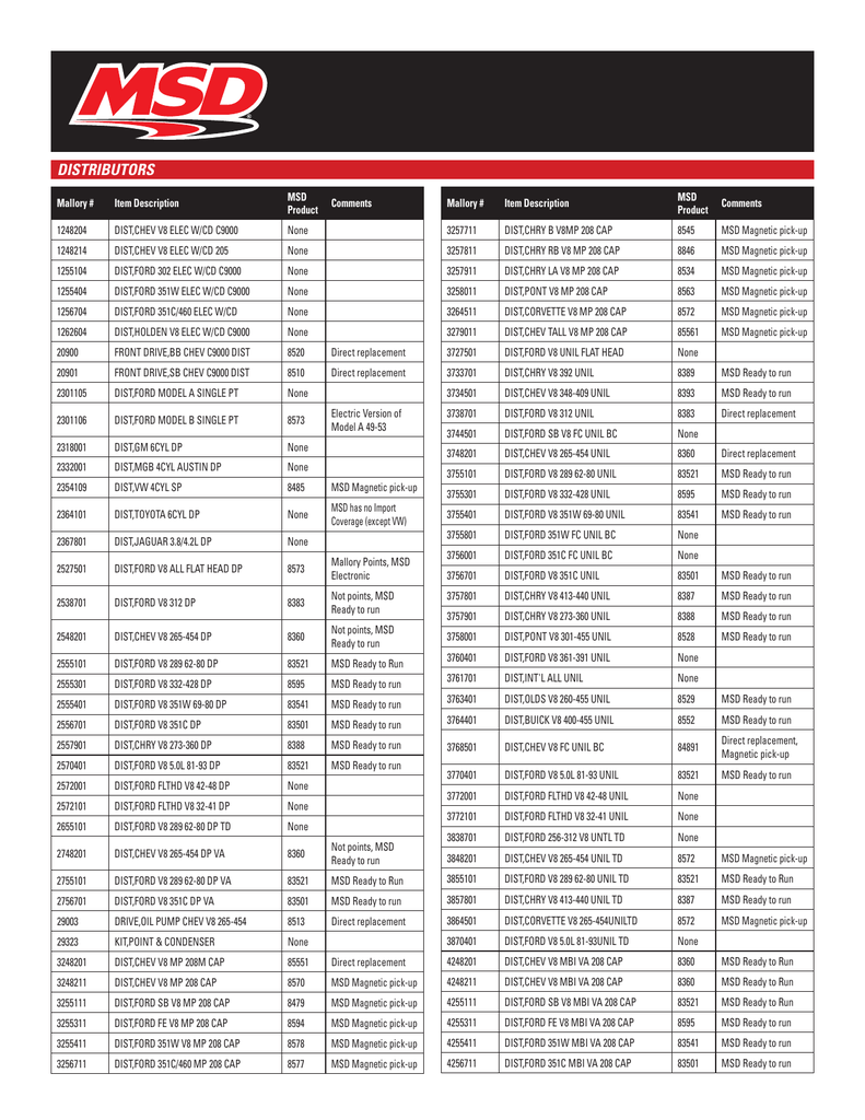
Mallory To Msd Cross Reference Guide Manualzz

Mallory Ignition 5048201

91 Dodge Dakota Radio Wiring Harness Diagram Liar 10balmoond
Incubator Using Arduino With Automatic Temperature And Humidity

Wrg 5168 850 Norton Wiring Diagram 1975

4 Prong 4 Wire Dryer Cord Diagram Wiring Diagram

Build A Simple Solar Powered Outdoor Light Solar Powered Outdoor

Lancing Manor Ice House Diagram
Need Help With Mercruiser 165 Hp Inline 6

10 Free Backyard Chicken Coop Plans Chickens Backyard Chicken

Grunged Fake Circuit Diagram Repeat Pattern Pattern Techno
