Mallory Hyfire Wiring Diagram

Wiring Procedure Figure 4 12v Battery Mallory Ignition

27e997 Mallory Hyfire 6853m Wiring Diagram Wiring Resources

Mallory Instructions Hyfire 206a 6al Wiring Diagram 6852m 6853m
Hyfire Cd Ignition System Figure 1 Mallory Ignition Mallory

Eb 0637 Wiring Diagram Mallory Comp 9000 Wiring Diagram Mallory
914world Com Mallory Hyfire

Recommend mallory s promaster coil p n or mallory s all of the wires of the hyfire 6a ignition control may be shortened as long as.
Mallory hyfire wiring diagram. It shows the components of the circuit as streamlined forms as well as the power and also signal links between the tools. If your vehicle has a ballast resistor in line with the coil wiring it is recommended to bypass it. Parts included in this kit. I ve got the older style mallory ignition amplifier and have already downloaded a wiring diagram to hook up to a unilite.
Mallory hyfire wiring question nastyz28 com. Do not use mallory s pomaste coil p n tachometers the yellow wire on note. 2a wiring method using adapters and harnesses sold separately special wiring adapters and harnesses simplify the installation of the hyfire vi electronic ignition control into newer vehicles. Mallory hyfire ignition wiring diagram file pdf book only if you are registered here.
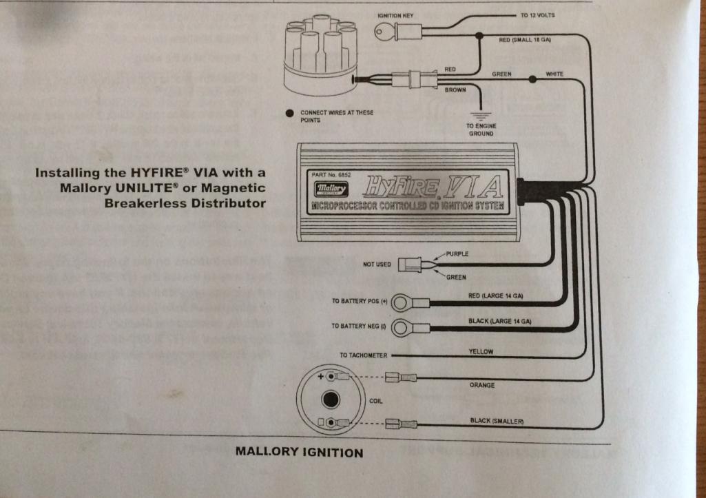
Locate one long red wire and one long black wire at the end plate of the hyfire iv electronic ignition control. Collection of mallory ignition wiring diagram. Mallory s promaster coil p n can also be used as well as most stock coils or aftermarket coils the yellow wire on the hyfire 6a ignition control provides a trigger signal for use the chart at right as a starting point. Mallory hyfire 6a wiring diagram note.
1 hyfirefi vi electronic ignition control part no. Installation instructions 3 mallory www mallory ignition com 915 857 5200 fa 915 857 3344 ballast resistor. Of terminals on both ends of the module and follow the corresponding diagram. These adapters and harnesses allow you to connect the hyfire vi electronic ignition control between the ignition coil and the factory coil connector.
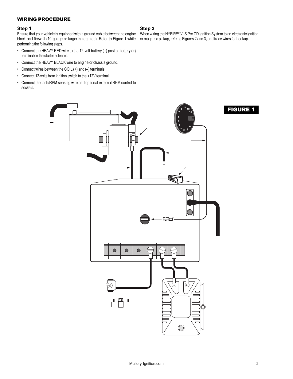
Wiring procedure step 1 refer to figure 3 ensure that your vehicle is equipped with a ground cable between the engine block and firewall 10 gauge or larger is required. Now my question is where does the stock tach lead hook up to does it go to the coil or to the coil hook up on the ignition box. 685 will not work properly with odd fire or semi even fire v6 applications. The rpm limiter in the hyfire fi vi part no.
Mallory hyfirefi vi electronic ignition controls are not compatible with distributorless systems or positive ground applications. 6852m 6 a and 6853m 6 al installation instructions form 1522tl general information the features of the hyfire 6 a and hyfire 6 al are the same with one exception the hyfire 6 al includes a single stage. A wiring diagram is a simplified standard pictorial depiction of an electrical circuit.

Cn 7661 Mallory 685 Ignition Wiring Camaro Forums At Z28com

Linhui For Opel Vectra 5 Buttons Uncut Blade Original Remote Blank
Mallory Instructions Hyfire 206a 6al Wiring Diagram 6852m 6853m
