Mallory Ignition Hyfire Wiring Diagram

27e997 Mallory Hyfire 6853m Wiring Diagram Wiring Resources

Mf 7816 Mallory Hyfire 6853m Wiring Diagram Schematic Wiring
Mallory Ignition Mallory Hyfire 6a And 6al Series Electronic

Nn 2820 Mallory Pro Comp Ignition Wiring Diagram Download Diagram
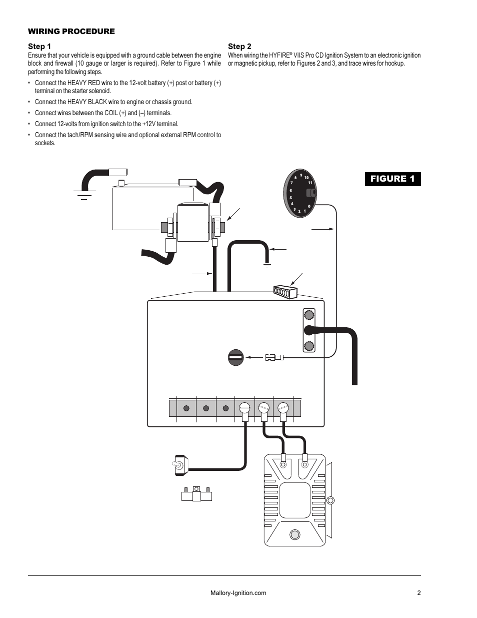
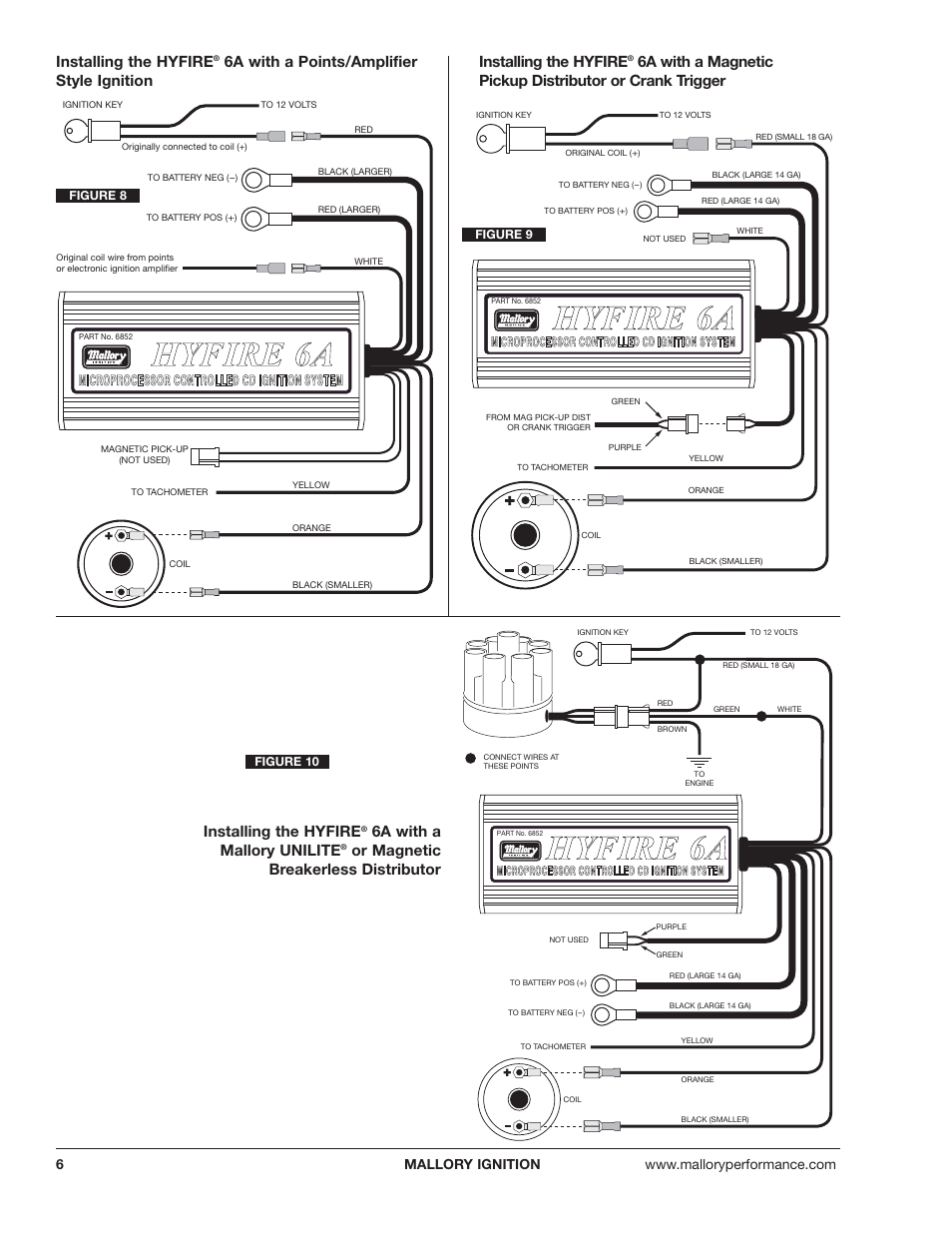
Hyfire Cd Ignition System Figure 1 Mallory Ignition Mallory

Eb 0637 Wiring Diagram Mallory Comp 9000 Wiring Diagram Mallory

Mallory hyfire ignition wiring diagram file pdf book only if you are registered here.
Mallory ignition hyfire wiring diagram. The rpm limiter in the hyfire fi vi part no. With a vintage design for that classic look the hyfire looks as good as it per. The mallory hyfire ignition. 1 hyfirefi vi electronic ignition control part no.
It shows the components of the circuit as streamlined forms as well as the power and also signal links between the tools. Parts included in this kit. Mallory hyfirefi vi electronic ignition controls are not compatible with distributorless systems or positive ground applications. Unilite distributor vacuum chamber and the carburetor.
Installation instructions 3 mallory www mallory ignition com 915 857 5200 fa 915 857 3344 ballast resistor. Mallory s promaster coil p n can also be used as well as most stock coils or aftermarket coils the yellow wire on the hyfire 6a ignition control provides a trigger signal for use the chart at right as a starting point. Mallory ignition hyfire 6a and 6al series electronic msd mallory hyfire 6a install on 3 2 carrera pelican parts forums mf 7816 mallory hyfire 6853m wiring diagram schematic thesamba com performance engines transmissions view topic mallory ignition hyfire 6a and 6al series electronic msd mallory hyfire 6a install on 3 2 carrera pelican parts forums mf 7816 mallory. Ignition controls hyfire vi ignition system part no.
685 will not work properly with odd fire or semi even fire v6 applications. Collection of mallory ignition wiring diagram. Mallory hyfire wiring question nastyz28 com. Routing wires the hyfire wires should be routed away from direct heat sources such as exhaust manifolds and headers and any sharp edges.
A wiring diagram is a simplified standard pictorial depiction of an electrical circuit. If your vehicle has a ballast resistor in line with the coil wiring it is recommended to bypass it. 685 advanced hyfire vi ignition system part no. The purpose of an ignition ballast resistor between the ignition switch 12v and the ignition coil positive terminal is to restrict current flow through the ignition coil.
A familiar name in ignition performance is back. Now my question is where does the stock tach lead hook up to does it go to the coil or to the coil hook up on the ignition box.

Cn 7661 Mallory 685 Ignition Wiring Camaro Forums At Z28com

Mallory Hyfire Ignition Youtube
Linhui For Opel Vectra 5 Buttons Uncut Blade Original Remote Blank

Ad Ebay 8 Pc Denso Iridium Power Spark Plugs For Chevrolet G10

Pin By Waji Cars On Oto Cars Motor Car Ohio Vehicles

Pin By Waji Cars On Oto Cars Motor Car Ohio Vehicles

Pin By Waji Cars On Oto Cars Motor Car Ohio Vehicles

Pin By Waji Cars On Oto Cars Motor Car Ohio Vehicles
