Mallory Ignition Tach Wiring Diagram

Mallory Unilite Distributor Manual

Mb 9245 Mallory Ford Ignition Coil Wiring Diagram Schematic Wiring

Nf 0247 Mallory Hyfire Wiring Diagram On Vw Coil Wiring Diagram

Ct 8466 3 Wire Distributor Wiring Diagram Free Diagram

Nn 2820 Mallory Pro Comp Ignition Wiring Diagram Download Diagram
Mallory Unilite Hook Up Br For 72 Datsun 240z

This will minimize loose connections that could cause problems later.
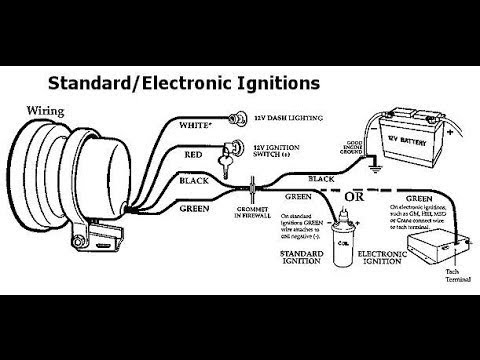
Mallory ignition tach wiring diagram. Older voltage triggered tachometers this type of tachometer cannot be triggered from the low voltage tach output of modern capacitive discharge ignition systems. Use separate battery leads for ignition and tach to avoid excess voltage drop. It shows the components of the circuit as streamlined forms as well as the power and also signal links between the tools. Mallory s tach adapter eliminates this problem.
Unilite distributor vacuum chamber and the carburetor. Mallory pro tach i iv and iv. Connect the mallory adapter part no. Got a vintage mallory tach i m putting in my car.
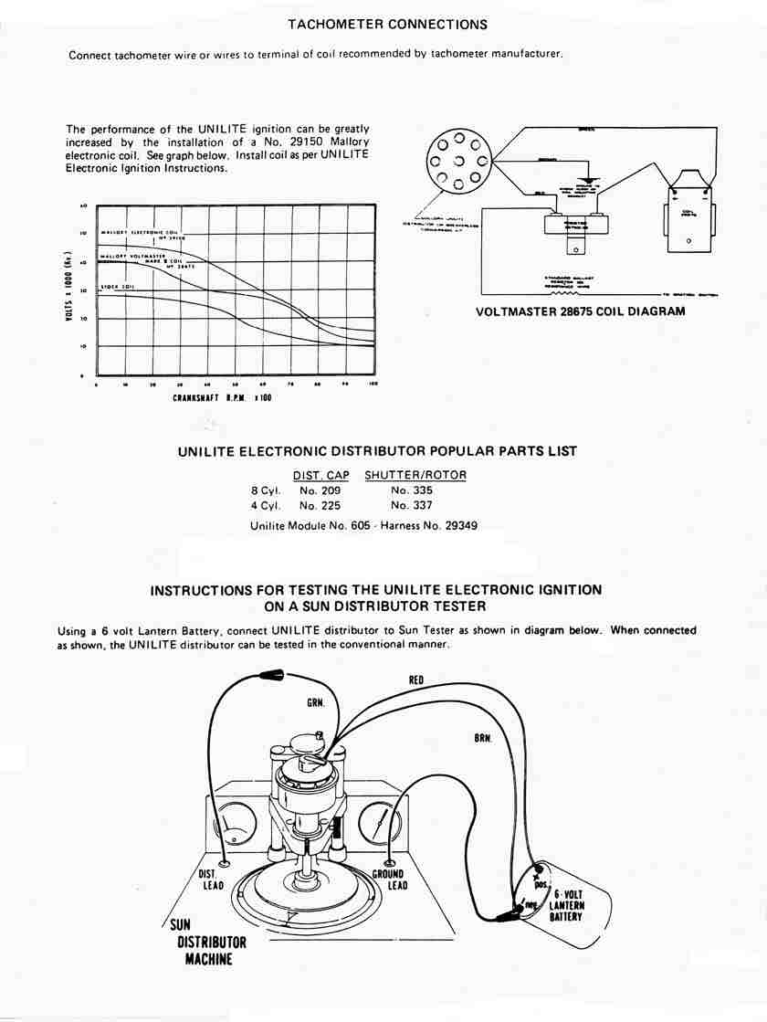
Wherever possible solder wire connections and avoid crimp type connectors. Currently working on changing my ignition to a mallory super mag with i have wiring diagram for all the components but none of them exactly aug 31 please help. Red ignition wire such as mallory pro sidewinder by the actual tachometer manufacturer. 6al and msdtm 6 series ignition mallory distributor tune up parts distributor cap 209m rotor 309m unilite module 605 high energy distributor cap 208m optional accessories for the.
Strip the end of the trigger wire for the tachometer and place a female to female connector to it. Avoid connecting tach power and ignition power leads together. Run enough wire to reach the msd ignition control box mounted on the firewall in the engine compartment. Mallory tachometer wiring diagram the pro tach tachometers may be installed on any 12 volt ignition on 4 cylinder 6 cylinder even fire make sure these four wires are not pinched or cut.
Collection of mallory ignition wiring diagram. Mount the mallory fuel injection tach adapter away from hot wiring diagrams for this unit are shown on the back of this instructions sheet. Watch as the two guys garage crew guide us through the installation of a mallory distributor bringing an old ignition system into the new millennium. Figure 1 unilite wiring diagram using ballast resistor ignition module female connector engine ground all other wires originally connected to the coil terminal.
29078 as shown below. A wiring diagram is a simplified standard pictorial depiction of an electrical circuit. The purpose of an ignition ballast resistor between the ignition switch 12v and the ignition coil positive terminal is to restrict current flow through the ignition coil.

Fc 6753 Vintage Tachometer Wiring Download Diagram
Simple Tach Install For Hei Distributor Re Upload Youtube

Pin On Truck Mods

Pin On Stuff I Like


Mcleod Decal Car Memorabilia Racing

1951 Mercury Sport Sedan With Images Sports Sedan

1950 Buick Roadmaster Riviera Deluxe G209 Kissimmee 2019 Met

2001 Bentley Arnage T7 Indy 2018 Bentley Arnage Bentley

1977 Pontiac Grand Prix 63 000 Actual Miles Rare White Interior

Crower Fuel Injection Staggered Bb Chevy Rebuilt Alky Std Deck

1959 Chrysler 300e Convertible F136 Indy 2018 Chrysler

1964 Chevy Impala Coupe Bing Images Chevy Impala Impala 1969
