Mallory Ignition Wiring Diagram Ford Iv

Wiring Procedure Figure 4 12v Battery Mallory Ignition

Eb 0637 Wiring Diagram Mallory Comp 9000 Wiring Diagram Mallory
Mallory Hyfire Wiring Diagram Wiring Diagram

Kl 7344 Coil Ballast Resistor Wiring Diagram Msd 6al Wiring

Mallory 685 Ignition Wiring Camaro Forums At Z28 Com
6487aa Mallory Promaster Coil Wiring Diagram Wiring Resources

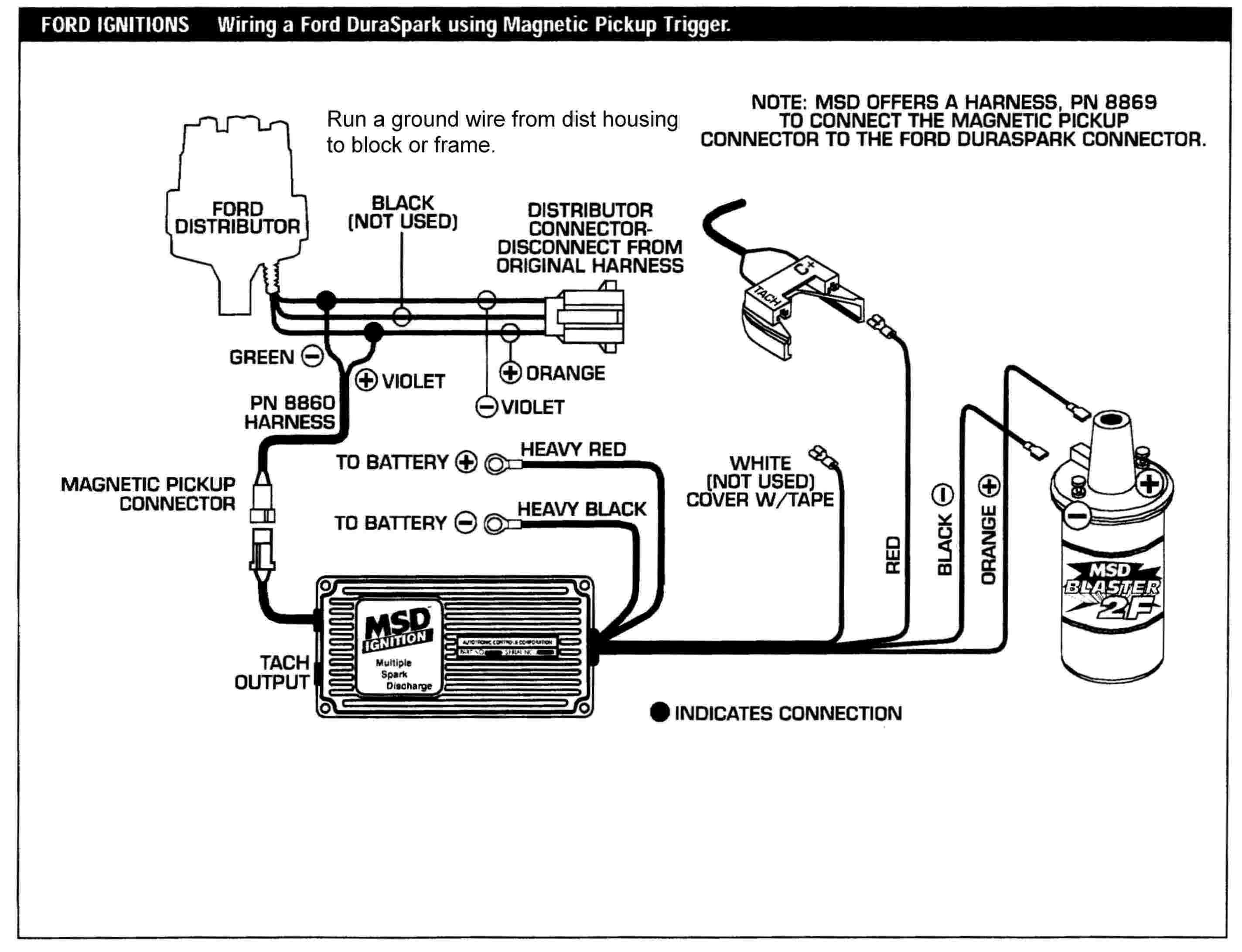
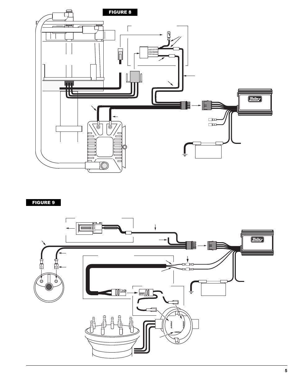
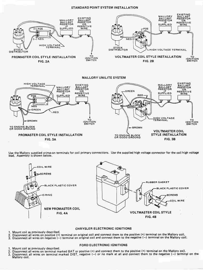
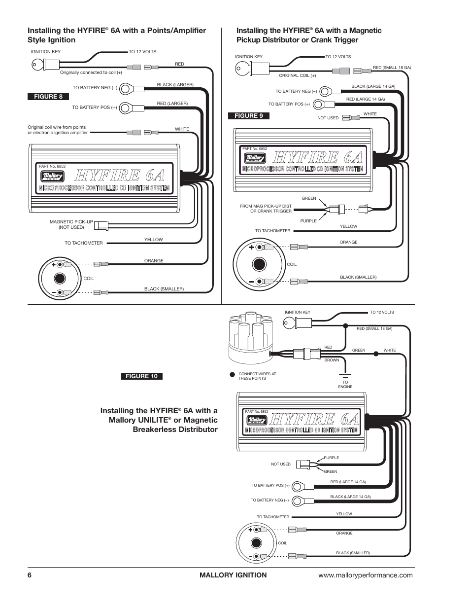
Installation instructions 3 mallory www mallory ignition com 915 857 5200 fa 915 857 3344 ballast resistor.
Mallory ignition wiring diagram ford iv. However the tach s proportional controller that limits rpm will not function with the hyfire vi. Hyfirefi iv electronic ignition control. By the late 1960 s the detroit plant had become too small and boots mallory began moving his father s company to carson city nevada in 1969. Mallory proportional rpm limiter part nos.
Even today mallory continues to build performance ignition products for ford motor company vehicles. Ask for one from the 1970 s. It shows the components of the circuit as streamlined forms as well as the power and also signal links between the tools. Magneto ignition systems super mag ii sprintmag super mag read online or download pdf mallory diagrams on pages 2 and 3 for all additional wiring.
If your vehicle has a ballast resistor in line with the coil wiring it is recommended to bypass it. Mallory wiring diagram in ignition hbphelp from mallory ignition wiring diagram source hbphelp me mallory wiring diagram wiring diagram from mallory ignition wiring diagram source anynews co mallory ignition wiring diagram 2 lenito at wellread from mallory ignition wiring diagram source wellread me. Mallory pro tach i iv and vi the rpm needle and shift light will work with the hyfire vi. Mallory pro tachfi i iv and vi the rpm needle and shift light will work with the hyfire fi vi.
However the tach s proportional controller that limits rpm will not function with the. So will a msd or mallory distributor with a ford style magnetic pickup these are the distributors without a built in module. Mallory supplied much of the original equipment ignition components for ford through 1948. Step 2 choose one method listed below for wiring the hyfirefi iv electronic ignition control 2a 2b or 2c 2a wiring method using adapters and harnesses sold separately special wiring adapters and harnesses simplify the installation of the hyfirefi iv electronic ignition control into newer vehicles.
Mallory proportional rpm limiter part nos. Routing wires the hyfire wires should be routed away from direct heat sources such as exhaust manifolds and headers and any sharp edges. Next you need to purchase a gm hei module. 641 4 641 6 641 8 642 643 and 644 will not function with the hyfire vi electronic ignition controls.
Collection of mallory ignition wiring diagram. Locate one long red wire and one long black wire at the end plate of the hyfire iv electronic ignition control. Wiring procedure step 1 refer to figure 3 ensure that your vehicle is equipped with a ground cable between the engine block and firewall 10 gauge or larger is required.

Mallory Unilite Wiring Diagram Sbc Diagrams Schematics Inside
12p12o Diagram Schematic Mallory Hyfire Ignition Wiring Diagram

122 Pro Comp Hei Tach Wiring Diagram Wiring Library
Mallory Ford Wiring Diagrams Liar Repeat24 Klictravel Nl

7972f Mallory 6a High Fire Wiring Diagram Wiring Library

27e997 Mallory Hyfire 6853m Wiring Diagram Wiring Resources
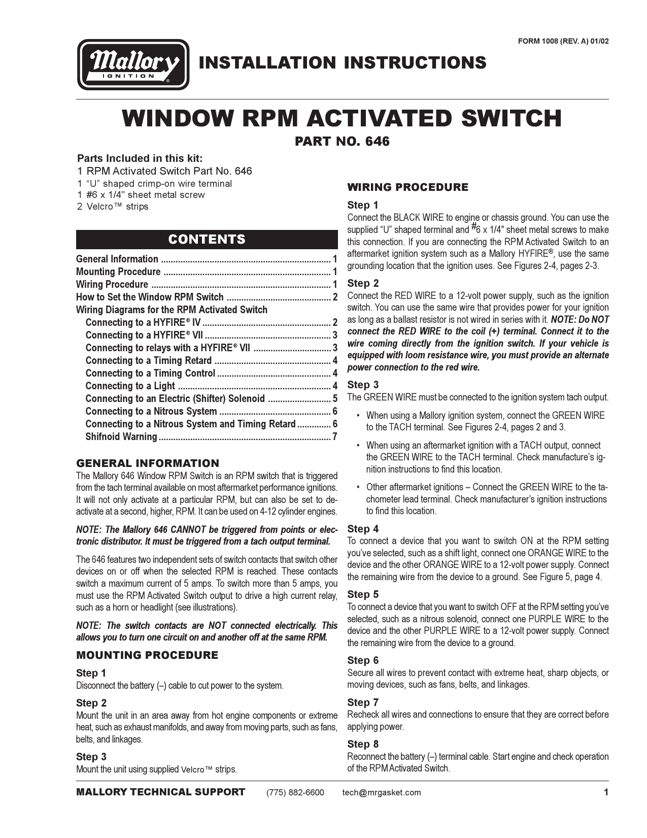
Mallory 646 Rpm Switch Installation Instructions Manualzz

Mf 7816 Mallory Hyfire 6853m Wiring Diagram Schematic Wiring
Https Www Manualshelf Com Manual Mallory Ignition Mallory Hyfire Iv Series Ignition System 692 697 Owner Manual English Html

Mallory Electronic Distributor Wiring Diagram Circuit Kuiyt
Mallory Promaster Wiring Diagram Mallory Distributor Wiring

Mallory Fuel Pump Wiring Diagram Wiring Diagram
Boat Supposed To Have An Ignition Module